Xian Yang Tee

Special expertise · Active thermal control (ACT)

Active thermal control: how I hold a stage where I want it, and prove it.

In thermoelectric and Nernst measurements, temperature is the measurement: a deliberate ΔT across a 3 mm crystal makes a nanovolt-level signal, and any drift, gradient or heat leak becomes false signal. This page is the thermal control I built to stop that, problem by problem.

WhereHomebuilt dipper cryostats, PhD, NTU 2009–2014 Range2 K to 300 K, in fields up to 16 T AlsoOperated a dilution refrigerator to about 10 mK

Part 1 of 4

My approach to ACT

Architecture, sensing and timing decide whether the loop can work at all.

1.1 · The control loop

What I control, and what I design out.

Active thermal control loop A setpoint and a calibrated sensor feed a PID controller, which drives a heater on the stage. The stage carries the sample. Disturbances act on the stage: heat leaking down wires, exchange gas, radiation, and the sample heater itself. A stability gate decides when the measurement may start. SetpointRECIPE · RAMP PID controllerGAINS PER RANGE HeaterHEATER RANGE Stage + sampleLOW MASS · WEAK LINK Calibrated sensorPLACED AT THE SAMPLE Stability gate|T−SET| AND σ(T) OK? MeasureONLY WHEN SETTLED WIRES GAS RADIATION DISTURBANCES I DESIGNED OUT
The loop I built in each probe. Active control handles what is left after the architecture has designed out the disturbances (red).

Active thermal control is a feedback loop: a sensor reads the stage, a controller compares it with the setpoint, a heater corrects it. In practice the loop is the easy part. It only works if three other things are right first.

  • The architecture. Heat paths are designed so the loop has little to fight: weak links, low thermal mass, heat-sunk wires, vacuum and radiation shields.
  • The sensing. The sensor is calibrated, trusted in the magnetic field, and placed where the sample really is.
  • The timing. Nothing is measured until the loop has settled, judged by data, not by a fixed wait.
  • Range controlled2 K (pumped pot) to 300 K
  • ControllerLake Shore 336, two PID loops
  • Sensors8 Cernox, 1 RuO₂, calibrated
  • Fieldup to 16 T
  • Signal it protectednanovolts, resolved to ±3 nV

Part 2 of 4

The problems I solved

Grouped by architecture, sensing, control and thermal debug.

2.1 · Problem by problem

Every one of these turned up in my own probes.

  1. 01Run the stage from 2 K to 300 K without boiling off the helium
  2. 02Get below the 4.2 K of the helium bath
  3. 03Stop heat leaking down the wires
  4. 04Stop gas and radiation coupling the sample to its walls
  5. 05Thermometers that read differently in a magnetic field
  6. 06The sensor is not where the sample is
  7. 07Measure the temperature difference itself
  8. 08A loop that overshoots, or crawls
  9. 09Knowing when the temperature has settled
  10. 10The sample heater kicking the stage out of regulation
  11. 11Repeat runs that disagreed by 3–7%
  12. 12Thermal voltages at every joint
  13. 13A probe generation that was wrong by design

Architecture: designing where heat may flow

01PhD

Run the stage from 2 K to 300 K without boiling off the helium

Why it’s hard
A hot stage bolted to a 4 K bath dumps its heat straight into the helium.
What I did
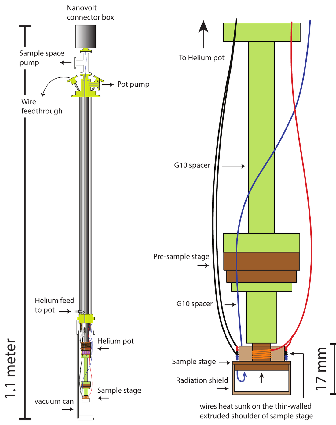
Hung the stage from the helium pot through G10 glass-epoxy spacers, a poor conductor, with a regulated OFHC copper pre-sample stage in between. Tuned stainless-steel weak links and copper strong links over successive probe generations.
Result
One probe measures anywhere from 5 to 300 K, with the bath undisturbed.
02PhD

Get below the 4.2 K of the helium bath

Why it’s hard
Liquid helium boils at 4.2 K at atmospheric pressure, the floor of a plain dipper.
What I did
Built a helium pot fed from the bath through a capillary, with its own pump port. Pumping on it lowers the boiling point.
Result
Base temperature about 2 K.
03PhD

Stop heat leaking down the wires

Why it’s hard
Every lead is a thermal path from room temperature straight to the sample.
What I did
Heat-sank every lead on copper bobbins at the 4 K flange, around a thin-walled shoulder on the stage, then on beryllium-oxide chips. Used low-conductivity phosphor-bronze for thermometry.
Result
Lowest base temperature and thermal noise the design allowed.
04PhD

Stop gas and radiation coupling the sample to its walls

Why it’s hard
Residual gas and radiation from the 4.2 K can give the sample an uneven temperature and a background thermal voltage.
What I did
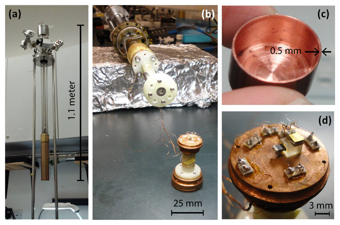
Pumped the sample space below 1×10⁻⁶ mbar and enclosed the sample in a 0.5 mm-wall copper radiation shield at stage temperature.
Result
The background thermal voltage was removed, with differential readings cancelling what remained.

Sensing: a loop is only as good as its thermometer

05PhD

Thermometers that read differently in a magnetic field

Why it’s hard
A sensor whose reading shifts with field silently moves the setpoint, and the data with it.
What I did
Calibrated at least eight Cernox sensors against references down to 1.8 K, built the controller curves, and characterised their magnetoresistance at 0, 1, 7 and 14 T. Fitted an 8th-order log-polynomial for a RuO₂ sensor.
Result
Setpoints that stay true from zero field to 14 T.
06PhD

The sensor is not where the sample is

Why it’s hard
I documented a few-tens-of-mK offset across one copper-block link, and a sensor millimetres away lags the sample during changes.
What I did
Moved the control sensor next to the sample on a sapphire block, which conducts heat but not electricity, and took data only once sensor and sample had both reached equilibrium.
Result
No data taken during a transient.
07PhD

Measure the temperature difference itself

Why it’s hard
Thermopower and Nernst signals are divided by ΔT, so any error in ΔT is an error in the result.
What I did
Built differential type-E thermocouples from 25 µm wire, spot-welded with no solder or paste, checked each joint in liquid nitrogen, and converted with NIST reference polynomials.
Result
A direct, solder-free ΔT reading across the crystal.

Control: making the loop behave

08PhD

A loop that overshoots, or crawls

Why it’s hard
Thermal mass and heat leaks change by orders of magnitude between 2 K and 300 K, so one set of gains cannot work everywhere.
What I did
Ran two PID loops on a Lake Shore 336, one on the stage and one on the pre-sample stage, tuned gains per temperature range (for example P = 200, I = 50, D = 0 from 4 to 60 K) and set heater ranges for authority without overshoot.
Result
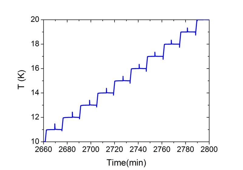
Automated 1 K steps that settle, measure and move on in about 14 minutes.
09PhD

Knowing when the temperature has settled

Why it’s hard
A fixed waiting time is either too short, so data is wrong, or too long, so runs waste days.
What I did
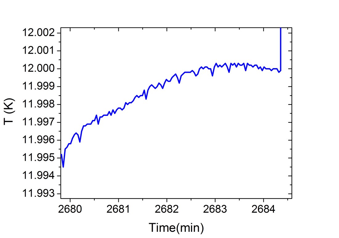
Gated every measurement on data: the distance from setpoint and the standard deviation of temperature over a time window, coded into the LabVIEW program.
Result
No point taken in a transient, and runs that go overnight unattended.
10PhD

The sample heater kicking the stage out of regulation

Why it’s hard
Switching the gradient heater on as a step disturbs the loop it sits on.
What I did
Ramped the sample heater on and off along a smooth profile, and switched it off automatically at the end of each sequence.
Result
The stage stays in regulation while the gradient is applied.

Thermal debug: finding the heat that should not be there

11PhD

Repeat runs that disagreed by 3–7%

Why it’s hard
Thermal measurements that do not repeat cannot be trusted, however low the noise.
What I did
Traced it to the joint between sample and stage, replaced it with silver paste annealed in oxygen, moved a sensor next to the sample and added 1 K-pot cooling.
Result
Repeat runs agreed within 1%.
12PhD

Thermal voltages at every joint

Why it’s hard
Any joint between dissimilar metals at different temperatures generates a voltage, at the level of the signal.
What I did
Clamped rather than soldered at room temperature, and anchored all solder joints to one temperature on BeO chips.
Result
Joints no longer added false signal.
13PhD

A probe generation that was wrong by design

Why it’s hard
Background offsets above 10,000 nV, far above the signal.
What I did
Traced the cause to the probe design itself rather than the sample or electronics, and rebuilt it.
Result
The next generation came in at 400 nV.

Part 3 of 4

The evidence

The probe I designed, the sensors I calibrated and the control loop at work.

3.1 · From my thesis and data

The probe, the sensors and the loop in action.

Schematic of the Nernst probe showing helium pot, G10 spacers, pre-sample stage, sample stage and radiation shield
From my thesis, Fig. 2.9: the Nernst probe. The sample stage hangs from the helium pot through G10 spacers and a copper pre-sample stage; wires are heat-sunk on the stage shoulder before reaching the sample.
Photographs of the probe, sample mounting, the thin radiation shield and the sample stage
From my thesis, Fig. 2.10: the probe, a sample mount, the 0.5 mm radiation shield and the copper sample stage.
Stage temperature stepping in 1 kelvin increments from 10 to 20 kelvin over about two hours
My data: automated 1 K steps from 10 to 20 K, each settling, measuring and moving on in about 14 minutes.
Stage temperature converging on the 12 kelvin setpoint
My data: one step zoomed in. The stage converges on the 12 K setpoint; the program waits for it to settle before it measures.
  • Thermometers calibrated8 Cernox, 1 RuO₂
  • Calibration range1.8 – 320 K
  • In-field check0, 1, 7, 14 T
  • Gradient sensortype-E thermocouple, 25 µm
  • Applied gradient~0.1 K/mm, ~1 mW
Honest scope. Everything above is my own hands-on work in the 2 K regime. Our lab’s DR500 dilution refrigerator reaches about 10 mK; I operated it and ran its cooldowns, but we did not set up an experiment on it before I finished. The two sections below explain how it controls temperature and how I prepared for it.

Beyond 2 K · How a dilution refrigerator works

Cooling by "evaporating" helium-3 into helium-4.

Getting to about 1 K. A pulse-tube cryocooler, a closed-cycle refrigerator with no liquid helium to refill, cools the first two plates to roughly 50 K and 3 K. The incoming helium is then condensed and expanded through a flow restriction, which takes it below about 1 K.

The key trick. Below about 0.87 K, a mixture of helium-3 and helium-4 separates into two liquid phases, like oil and water: a lighter phase that is almost pure helium-3 floating on a heavier phase that is mostly helium-4 with a few percent helium-3 dissolved in it. When a helium-3 atom crosses from the rich phase into the dilute phase, it absorbs heat, just as a molecule does when a liquid evaporates. That crossing happens in the mixing chamber, the coldest point of the fridge.

Keeping it going. The dilute phase connects to the still, held near 0.7 K. There, helium-3 evaporates far more readily than helium-4, so pumping on the still removes almost only helium-3. That keeps drawing helium-3 across the phase boundary in the mixing chamber. The pumped gas returns down the condensing line, is pre-cooled by heat exchangers against the outgoing dilute stream, and rejoins the rich phase: a continuous cycle.

Cooling power. The heat a dilution fridge can absorb falls roughly as the square of temperature (Q̇ ∝ ṅ3T², where ṅ3 is the helium-3 flow). At 10 mK the budget is microwatts, so every wire, support and radiation path matters far more than at 2 K.
Dilution refrigerator, simplified Stacked plates: pulse-tube stages at about 50 K and 3 K, the still near 0.7 K, heat exchangers, and the mixing chamber near 10 mK where a helium-3 rich phase floats on a dilute phase. A pump removes helium-3 from the still and returns it down a condensing line. PULSE TUBE · ~50 K PULSE TUBE · ~3 K Still He-3 EVAPORATES ~0.7 K HEAT EXCHANGERS He-3 RICH PHASE DILUTE PHASE He-4 + ~6% He-3 Mixing chamber~10 mK COOLS WHERE He-3CROSSES THE BOUNDARY EXPERIMENT PUMP CONDENSING LINE He-3 OUT DILUTE STREAM
Simplified dilution refrigerator. He-3 is pumped from the still, returned down the condensing line, and cools the mixing chamber as it crosses into the dilute phase.

Beyond 2 K · Thermal control at millikelvin

The techniques, and how I prepared to use them.

  • Staged cooling. Each plate, from 50 K to the mixing chamber, intercepts heat before it reaches the next. Wires and supports are anchored at every plate on the way down, so the coldest stage only sees what the stage above lets through.
  • Radiation shields on each stage, because a warm surface in view of the mixing chamber can exceed its entire cooling budget.
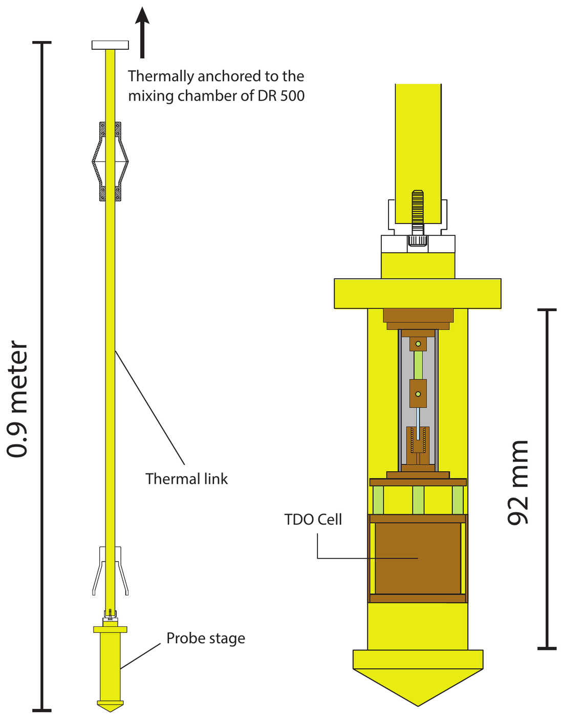
  • Thermal links. In cold-finger mode an experiment bolts directly to the mixing chamber. In top-loader mode it rides on a long probe and is cooled through a gold-plated OFHC copper link to the mixing chamber, which avoids warming the whole fridge to change samples.
  • Temperature control with heaters on the still and mixing chamber and resistance thermometers, typically ruthenium oxide, read with very low excitation so the thermometer does not heat itself.
  • Cooldown. Operating the fridge meant running the pulse-tube pre-cool, condensing the mixture and starting circulation, while monitoring each stage's temperature as it came down.

To prepare an experiment for it, I designed the tunnel-diode-oscillator cell to fit the top-loading probe, with three thermally separated zones: an electronics stage in its own radiation can, a coil zone isolated on G10 rods, and a sample stage with its own sensor and heater, holding the sample on a sapphire rod inside the coil without touching it. The oscillator was first tested at 77 K in liquid nitrogen; mounting the cell in the fridge was the next step when I finished.

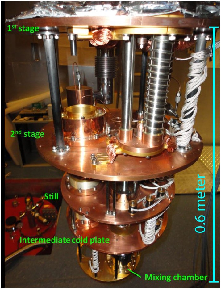
Photograph of the DR500 dilution refrigerator with vacuum jacket removed, showing pulse-tube stages, still, cold plate and mixing chamber
From my thesis, Fig. 5.8: the DR500 with its vacuum jacket removed. Pulse-tube stages, still, intermediate cold plate and mixing chamber are labelled.
Schematic of the top-loading probe with thermal link to the mixing chamber and the TDO cell on the probe stage
From my thesis, Fig. 5.9: the top-loading probe, cooled through a gold-plated copper link to the mixing chamber, with the TDO cell I designed on its stage.

Part 4 of 4

Why it matters to you

My thermal work was in cryostats, not test handlers. The engineering is the same.

Why it matters to you

The same physics as thermal control in test, at a different scale.

My thermal work was in cryostats, not test handlers. The engineering problems are the same, and the 2 K work is where I did them hands-on.

  • Heater, sensor and PID loop on a stageThermal head regulating a device under test
  • Sensor placement and sensor–sample lagHead temperature vs. die temperature, thermal offset
  • Annealed silver-paste contactThermal interface material and contact pressure
  • Low thermal mass, tuned gains per rangeResponse time vs. overshoot across power levels
  • Stability test before measuringSoak and settle criteria
  • Thermal EMF, gradients, heat leaksRoot-causing readings that drift with temperature